Class II ceramic characterisation
DC bias droop → reference library match
Compares a measured droop against reference C-DC-bias curves at the same case, value and absolute bias voltage, and reports which ratings remain consistent.
Reading
Match tolerance
A rating stays in the candidate list if the reference band at your bias comes within this many percentage points of your reading.
Fixture offset
Subtracted from every reading before matching. Calibrated on a known 0805 0.1 µF X7R 100 V part: 47.2% measured at 50 V and 73.1% at 90 V, against reference bands of 36.2–42.4% and 64.5–68.9% — a constant +4.5 pt. Most likely AC drive level above the reference 1.0 Vrms. Set to 0 to see raw readings.
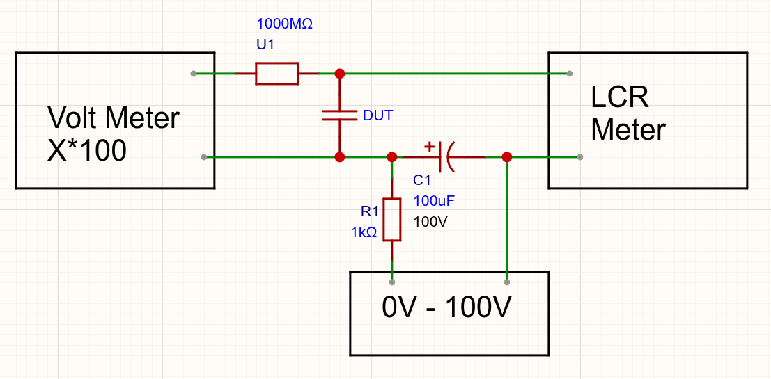
Supply may go as high as C1’s voltage rating allows. Multiply the
voltmeter reading by 100 — particularly where its internal resistance is around 10 MΩ
on the 100 V range. Tested successfully with the capacitance meters of an AN870
multimeter, a Hioki DT4282 and a BK Precision 879B.
bold band = candidatefaint = ruled outdashed = X5R
your reading
Sample log — 0 parts
| # | Label | Case | 0 V | Bias | V | ΔC | Reference family | Dielectric | Consistent ratings |
|---|